The LM324 Low-Pass Filter

I know, I know… It has been far too long since my last post.

The weather is cold and rainy so it’s CIRCUIT BENDING TIME!!!

I have been working on the Kawasaki Dual-CoolKeys lately. It’s a great keyboard with many independent features. By independent I mean, the keys are tied to a different timing resistor then the drums. Also, there is the ability to have one side play one set of instruments and the other side play another set. HOW COOL IS THAT?!?!?

I was digging through the usual circuit bending suspect’s blogs and was, as always, blown away by noystoise.com. The man is a super genius. And best of all, all his circuit bent gear looks so good.

He always has a filter (or two) in his projects. So, I wanted to have one too. How hard could it be? The answer is NOT HARD AT ALL!!!

I dug up some schematics for an LM324 Quad Op-Amp low-pass filter circuit and tried it out. I ran into one major problem with the integration of the low-pass filter and the Dual-CoolKeys. The Coolkeys has the drums output as the negative terminal going into it’s internal speaker. The keys are on the positive terminal. WHAT?!?!?

I spent a day just trying to figure out why the drum beats weren’t playing into the filter.

Once I figured out that each line into the speaker was actually individual sound outputs it made things easier. However, another issue is that if you connect the two outputs together with resistors to mix the sound, it shorts out the keyboard. I don’t know if it needs higher resistor values or what but that was annoying too.

Ultimately, I think I will just run each into an amplifier and mix them after that.

Back to the low-pass filter…

The filter is a simple build. Nothing fancy. The circuit only uses one op-amp from the LM324 so you still have 3 op-amps for other things. A great thing to add would be another filter for the drums. Or a high-pass filter… We will see.

lm324 opamp low-pass filter design

lm324 opamp low-pass filter design

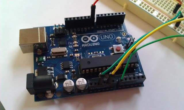
I bread boarded everything up and it worked great.

LM324 Low-Pass Filter

I played around a little with the values of the potentiometer and the other resistors. It took a while to find the right balance. If I remember correctly, the original schematic worked pretty well though.

LM324 Low-Pass Filter

It’s a great little circuit and super easy to build. Try it out and let me know how it goes.

Happy bending!!!

Kawasaki Dual-CoolKeys – Bending Heaven.

I was recently asked about the Kawasaki Dual-CoolKeys. The reader was asking if I had any experience with it or if I knew of any cool bend points.

Coincidentally, I had been messing around with a Dual-CoolKeys, not long before. I took some pics to document the device and wanted to share them.

kawasaki dual-coolkeys

I picked two similar Kawasaki keyboards up at Value Village for about 10 bucks. The guy looked at me super funny when I bought them. But hey, that’s part of the fun of circuit bending.

CIRCUIT BENDING AWESOMENESS #1


Upon opening up the Kawasaki Dual Keys keyboard, I noticed an amazing thing. The Dual Keys seems like it was built by someone who loves to circuit bend. Everything is modular and the whole keyboard comes apart beautifully. The screws are easy to reach and there ins’t much that is glued down. Really, the only glue is supporting the wires.

kawasaki dual-coolkeyskawasaki dual-coolkeyskawasaki dual-coolkeyskawasaki dual-coolkeys

CIRCUIT BENDING AWESOMENESS #2


I did some basic bend searching and found a resistor of particular interest. The thing that makes this perticular keyboard so perfect for circuit bending is that there is not one but at least two different timing resistors. This means that the timing for the drum track and the timing for the keyboard sounds are independently controlled .

kawasaki dual-coolkeys

I will be honest, it’s been a while since I was messing around with this Dual-CoolKeys, so I can’t remember if this resistor controlled the drum track timing or the keyboard sound timing (I’m pretty sure it was the keyboard) but either way, this is AMAZING!

IMG_0665

This is just the beginning. It’s easy to see the potential for circuit bending the Kawasaki Dual-CoolKeys into a much more amazing piece. I just wanted to get the ball rolling on the Dual-CoolKeys documentation. With some time and research, the Dual Keys, and the rest of the Kawasakies could be as popular as a Hing Hon or some of the more known synths out there.

If you have any information on the Dual-CoolKeys, feel free to shoot me an email or make a comment. If you write about, or have written about it, let me know and I’ll link to you.

Should you ever come across any of the Kawasaki line, (I have a few and they are all awesome) I highly recommend you pick it up.

DIY Drum Machine – Circuit Bending

I have been working on a diy drum machine for a while now. I wanted to post this video to show it’s functionality.

The core of this drum machine is from an electronic drum stick. You swing the stick and it makes drum sounds. The stick made 3 sounds; Snare, bass drum, and high hat.

DIY Drum Machine

When you swing the drum stick, it plays a snare sound. There are two buttons on the stick, that when pressed AND the stick is swung, play two more sounds. So this was easy to hook up to a 3-way switch with up as one button, down as another button, and middle was just like swinging the drum stick without pressing a button.

DIY Drum Machine

I rigged it up to a 555 timer and a 4017 decade counter and some pots and switches, and away it went. There is still some glitching that happens I think because of some switches which aren’t wired to ground to de-bounce them.

DIY drum machine - time signature controlerDIY drum machine - switches to control sound typeDIY drum machine - 555 timerDIY drum machine - 4017 decade counter

The 555 timer triggers the drum sound and advances the 4017. The 4017 sends a pulse through one of 10 3-way switches to hold the particular sound. The sound selection is set with the 3-way switch. I hope that makes sense.

Like I said, it’s a work in progress.

DIY drum machine - control board layout design

The case is from a kids toy (big surprise, I know). It was a light box for tracing. It use to have two lightbulbs inside and a semi-transparent screen. The cool thing about is that it has a battery compartment built in. All I had to do was modify it for the voltage I was using. I just shrunk it down. Easy (yeah right).

I painted it up white first and then spray painted a stencil of a fist on top of it. The body was also painted red. The final step for the paint job was to do some clear coat. All in all, a pretty sweet paint job.

Circuit Bending a DIY Drum Machine

In this video, you can see holes for the LEDs that will indicate which point in the sequence it’s at. I am having a heck of a time with that. It seems like, when connected, the sound plays but the LEDs don’t light up. I don’t know if it’s a lack of current or what. I have tried the LEDs in series and in parallel. Neither work now. The joke is, it all worked at one point when it was on a bread board. Upon soldering everything up, everything started changing. I suppose that is the nature of the beast.

I would love to hear your thoughts.

Happy Bending,
Nick

Arduino Sequencer

NEW POST!!!

To quote noystoise…

wow, its been a long time since i have posted anything here.

It has been ages since my last post. So much has happened (Including planning a wedding and getting married). With that said, I have still been circuit bending and building things.

My Arduino Uno Micro-Controler

Recently, I purchased an Arduino Uno micro-controller. This thing is awesome. It doesn’t have much to do with true circuit bending (I know someone will have a problem with that) but it is insanely powerful.

Here is what I have been playing around with in the last few weeks.

This little Arduino Sequencer project that I have been working on is super simple to build. Really all you need is an Arduino Uno (and a computer to program it with), breadboard, speaker, potentiometer (any value) and some wires.

All of the functionality comes from the programming. The code is simple too. Basiclly, you use the built in tone generator (it’s just a square wave generator) to read the value of a potentiometer and place the value of that the potentiometer into a variable. Then you play a tone based on that value, pause, play another tone, pause, play another, etc.

The subsiquent tones are based off the original tone, they are just multiples of that first value.

The program loops and starts all over again. That’s it!

Arduino uno diy sequencer

Here is the link to the tutorial that I followed originally. It has some schematics and in depth instructions about how to set it up and how the code works.
Arduino Tone Follower Tutorial

Here is the code:

/*
SecondHandSynth Digital Arduino Sequencer
https://secondhandsynth.wordpress.com/

Plays a pitch that changes based on a changing analog input

circuit:
* 8-ohm speaker on digital pin 8
* Breadboard
* Some resistors and wire

This example code is in the public domain.

Original code before modification came from
http://arduino.cc/en/Tutorial/Tone2

*/

void setup() {
// initialize serial communications (for debugging only):
Serial.begin(9600);

//boot up sound
int var = 100;
while (var < 500)
{
tone(8, var, 50);
delay(150);
var=(var+80);
}

}

void loop() {
// read the sensor:
int sensorReading = analogRead(A0);
int delayTime = 175;
int durationTime = 5000;

// print the sensor reading so you know its range
Serial.println(sensorReading);

// map the pitch to the range of the analog input.
// change the minimum and maximum input numbers below
// depending on the range your sensor's giving:
int thisPitch = map(sensorReading, 0, 1023, 50, 2000);

// print the mapped range
Serial.println(thisPitch);

// play the pitch:
tone(8, thisPitch * 2.5, durationTime);
delay(delayTime);
tone(8, (thisPitch * 2), durationTime);
delay(delayTime);
tone(8, (thisPitch * 1.5), durationTime);
delay(delayTime);
tone(8, (thisPitch), durationTime);
delay(delayTime);

//second string
thisPitch = thisPitch * .5;

tone(8, thisPitch, durationTime);
delay(delayTime);
tone(8, (thisPitch * 1.5), durationTime);
delay(delayTime);
tone(8, (thisPitch * 2), durationTime);
delay(delayTime);
tone(8, (thisPitch * 2.5), durationTime);
delay(delayTime);

//second string
thisPitch = thisPitch * 1.5;

tone(8, thisPitch, durationTime);
delay(delayTime);
tone(8, (thisPitch * 1.5), durationTime);
delay(delayTime);
tone(8, (thisPitch * 2), durationTime);
delay(delayTime);
tone(8, (thisPitch * 2.5), durationTime);
delay(delayTime);

//second string
thisPitch = thisPitch * .5;

tone(8, thisPitch, durationTime);
delay(delayTime);
tone(8, (thisPitch * 1.5), durationTime);
delay(delayTime);
tone(8, (thisPitch * 2), durationTime);
delay(delayTime);
tone(8, (thisPitch * 2.5), durationTime);
delay(delayTime);

}

Try it out for yourself and let me know how it works. If you have any questions, don’t hesitate to ask.

Thanks for reading and HAPPY BENDING!

Delay circuit with the melody making sequencer!

It was suggested to me by Iowanchef to add a pt2399 circuit to this crazy little bend.

Ask and thou shalt receive!

I had a soldered up pt2399 delay circuit just laying around doing nothing so I threw it in parallel with the sequencer’s speaker. I ran an output off to my guitar amp. It worked perfectly. CHECK IT OUT!!!

The video is a little long but there is some really cool sounds toward the end.

Now that I think of it… why didn’t I turn on the drum machine? Oh well, next time.

Happy Bending!

Little Composer – The Melody Making Sequencer

I can’t really finish my drum machine right now because I am waiting for some 3-way switches to arrive from ebay. I need to learn to stock up. I am way to impatient for this whole “12-21 days shipping from Thailand” thing.

What to do instead?
I picked up this second hand synth the other day. It’s called the Little Composer by Leap Frog.

05_03_2010 001

It’s really more of a musical learning toy for children. It has an 8 note measure that you can adjust each not from low to high C (only in the key of C, of course). The Little Composer has 7 voices. There are three instruments; piano, guitar and violin. There is also a woman voice that tells you what the note is. A, B, C, D, E, F, G… That is really annoying. And finally there is a dog, a cat, and a frog. These only sound good when they are clocked really high or really low.

05_03_2010 004

There are also a bunch of songs too but they are all lame. I suppose that they could be kind of cool clocked real low because the would go for a really long time but I don’t think I will include them in the final build.

05_03_2010 005

The ocatave has no sharps or flats. which is unfortunate. It would be awesome to have a full octave. Of course, if one were to add a pitch bend, one could hit any western key that they wanted.

05_03_2010 007

Naturally, that’s just what I did. I removed the timing resistor and added a pitch bend in series with about 5k ohms (i think),

Here comes the cool part. When you press the play button, this melody-maker only goes through the measure once. This is a real bummer. How is a child suppose to learn music if they can only play one measure at a time. So, I added an LFO from a 555 timer.

05_03_2010 003

It took me a little while to figure out how to make it work. I ended up just running a 10k out of the output from the 555 timer and going strait to the pin on the control circuit that handled the play button. That worked great. I thought I was going to have to do some weird thing with a transistor that I wouldn’t fully understand for the next couple of years. Luckily, that wasn’t the case.

So, if you tune the LFO frequency, as I am doing in the video below, you can get the melody maker to act as a sort of 8 note sequencer. SWEET RIGHT?!

Next, I think I am going to have to add the usual LFO to modulate the pitch and maybe even a tremolo. I’m also waiting on some frequency divider chips from ebay. Maybe one of those will make it in too.

05_03_2010 002

Happy Bending!

Drum Machine – Work in Progress

This is the project I am working on right now.

This is a drum machine that I am making. The core is from an old electronic drumstick that I found at a thrift store. It is opperated by swinging it just like a real drum stick and stopping it in mid air. When the electronic drumstick stops, it makes a sound.

The default sound is a snare but there are also two more sounds. If you hold one button and swing the electronic drum stick it makes a bass drum sound. The other button has a crash symbol.

The drum machine is being timed by a 555 timer and a 4017 decade counter. It will have a 3-way switch for every step in from the 4017. One for each sound. In addition, it will have an on/off switch and (if all goes well) a pitch adjustment for every step.

Happy bending!

Insect-A-Tron – (Mini-Keys circuit bending part2)

I can’t tell you how excited I am.

I just finished my mini-keys keyboard that I was working on (Mini-Keys — A little keyboard circuit bend (part 1)).

I’m so stoked on this that I can’t even think of a good way to tell about it. So, I’m just going to show you this second hand synth and let you be the judge.

mini-keys2 015

The paint job and design

First off, I am really excited about the paint job. It’s not what I envisioned when I first thought of the design but it definitely is the best thing I have made to date.

mini-keys2 017

It was inspired by the way the synth sounds when it’s oscillators are kicked on. It’s what I think insects sound like when they communicate with one another. Lot’s of super sonic chirps and squeaks.

mini-keys2 021

Anyway, this paint job was tough to do too because I kept screwing up. I must have repainted it 3 or 4 times. Doing the stencils was increadably difficult. I found the images I wanted and printed them onto paper. Then I cut out the silhouette with an exact-o knife. Because the paint kept sparaying under the stencil and screwing up the whole thing, I finally decided that tape wasn’t enough to hold it down. I mixed some Elemer’s glue and water and coated the back of the stencil. That did the trick.

mini-keyboard 019

After the painting was finished, I made a couple of images in photoshop to label the keyboard and to put “SECOND HAND SYNTH” on the back of the keyboard. I cut them out from the plain white printer paper they were printed on and glued them to the keyboard. I tried t be cool and write 2010 on the back. I don’t know why I thought that was a good idea but I did it.

I really liked the synth identifying decal. “Insect-A-Tron”. Howerever, as soon as I had done it I realized that it should have been Insect-O-Tron. Oh well.

I finished the paint job with two coats of clear gloss. I used a polyurethane which I think had a little stain in it (it is for wood projects). It turned the white paint a little yellow. Not a lot. But enough so that it doesn’t have the cool, cold white feel to it. I’m gonna use real clear coat next time.

Synth Controls

These are the controls on the left hand side. The top switch engages the oscillators. The bottom on is a bend that I found on my own circuit. It smooths out the warble of the oscillators. The Joystick in the center of the black panel controls the frequency of the oscillators. The black knob at the top of the picture controls the bottom switch’s saturation. I don’t exactly know what it is doing but is a bit like a depth knob on a flanger pedal.

mini-keys2 020

This is the pitch knob. It is a washer glued to a little 1M potentiometer. It worked out quite nice. I just wish it was black. Maybe I will paint it someday.

mini-keys2 026

This is the push botton switch that activates the custom dual oscillator chip that I added to the keyboard. I should have made it turn on the actual keyboards chip too.

mini-keys2 024

The problems with this synth

The main problem so far is that there is no volume control. I am gonna have to get the output resistance right and solder it in there. The signal comes out quite hit and clips a lot of the sound. I had to rig a little pot in series with the keyboard just to make the video. For the life of me, I have no idea why that wasn’t part of the design.

The second problem is that there is a switch on the right hand side that activates the oscillator chips. The circuit board is powered by a 9v battery but the keyboard is powered by two AA batteries. You have to open up the entire case to get the 9v out. I guess it’s a good thing that there is a on/off switch for the 9v but I don’t like how it’s impossible to get the 9v out without taking it apart.

mini-keys2 012

The third thing that I don’t like about this second hand synth is that some of the settings don’t make any sound. I wanted the most variety of sound so I didn’t dial in the resistances of the joystick very much. Because it’s not properly calibrated, when the timing resistance it too low, you get nothing.

Oh well.

Another problem is that the keyboard is a little filled up. There is so much packed into such a small case. Next time I will definitely map out where the wires will go before I get into that phase of construction.

mini-keys2 014

The last thing that I should have done is to label the controls. I originally intended to have interesting insectoid names for all the switches and knobs. I was a little impatient and went on with out doing it. Again, oh well. Maybe I will bust out a sharpie and write it all on.

Oh! And, I forgot to put in the LED’s too. There is one for each LFO. Oh well.

I don’t even know how many hours I put into it. Many. Too many. Not enough. I don’t know. Just to get it all glued into the case it took me 3-4 hours.

Here is the first video.

Also, please click on any of the pictures and check them out on Flickr.com. There are tons more pics and you can view the larger resolutions too.

Happy Bending!!!

Mini-Keys — A little keyboard circuit bend (part 1)

I have been working on a small but complicated project for the last week or so. Basiclly it’s a continuation of the last mini-keyboard circuit that I fried. I posted some pics in an earlier post.

The original project had a dual LFO powered by a 9V battery. I was using the 556 dual timer chip to accomplish this.

Long story shore; I fried the little guy and the 556 timer while trying to adapt the keyboard for wall power.

The new keyboard and circuit design

I was lucky in the fact that I had found almost the exact same keyboard the weekend before I fried it.

joystickStuff 005

I could just substitute it in for the old one and none would be the wiser.

The only problem was that I had fried the 556 chip and didn’t have another one. I could have gone to Radio Shack or bought some online. I didn’t really want to do either. The Shack is too expensive and ordering online takes too long. I had to come up with something else.

joystickStuff 006

I decided to practice what I preach and give the lm386 a go. So I followed the schematic on the datasheet and wired a square wave. And wouldn’t you know it… It worked.

The “square wave” seemed to act a little differently than the 555 timer square wave. It seemed to have more slope on the beginning and end of the square wave shape. I know this because I had it running an LED. The LED seemed to dim as the capacitor discharged.

Anyway, I wired up two of those lm386 oscillators and played around with them. Crossed a wire here, added a capacitor there. You know how it goes.

mini-keyboard 002

Mostly, the two LFO’s are effecting the pitch (vibrato if you will). One is directly effecting the pitch and the other one is modulating the first LFO and also operating a transistor gate which is almost acting like a tremolo.

All in all I came out with a pretty good design. One that I’m sure could be patched into just about anything with a timing resistor.

The fun stuff

The best part is the joystick. It operates the both LFO’s frequencies at the same time. LFO1 is the X-axis and LFO2 is the Y-axis.

mini-keyboard 003

The really cool thing is the second LFO. As I said, it operates a transistor gate for the first LFO. These different combinations make some really interesting modulation to the sound of the keyboard. But, it also is patched into the pitch resistor array at a different place than LFO1. So, when all is said and done, the sounds that you get are really quite diverse.

I have a switch that activates the second pitch controlling LFO2 (but not the transistor gate of LFO2) which basically gives the keyboard a super alien/insect sound. When I blast that sucker, I feel like I’m hearing ants communicate.

Painting

I have only just begun to paint this beast but so far it’s turning out pretty good.

mini-keyboard 019

IT’S REALLY COOL!!!

mini-keyboard 013

-videos and schematics coming soon in part 2

Potentiometers from an X-Box controller joystick! – a how to guide

In this entry I will show you how to take apart an x-box controller and then how to extract the joystick. I will also show you how to remove the spring from the joystick so that you don’t have the “return to center” action that the controllers come with.

But first…

The story

I was at my favorite place, a thrift store. While making my rounds, looking for second hand synths, I came across an old X-Box controller. I have seen other people use joy sticks in their circuit bending projects but I have never seen them for sale (mostly because I never though to look).
x-box controller - potentiometer

I know that the controllers have a lot of control and accuracy. So, I figured that there must be two potentiometers for each joystick. Otherwise, you couldn’t camp out in a tower, aim your gun at your opponent’s head and snipe him in the head. You would be able to do it if there were four buttons behind the joystick.

Naturally, I bought it.
Naturally, I took it apart.

inside an x-box controller - see the two potentiometers?

(note: in the above two pictures the controllers are different… this is because I didn’t take them. I stole them from somebody on the web. Sorry. I won’t do it again… in this post… )

There isn’t really much worth taking, besides the joystick potentiometers. The rest is just simple contact push buttons. Too bad really. For what they cost, I thought there would be much more inside.

The Joystick

The X-Box joysticks are just two potentiometers. Obviously, one is for the x-axis and one is for the y-axis.

joystickStuff 008

The pots measure at about 10k when they are fully pressed in one direction. They rest at about 5k with a small amount of resistance opposite the 10k side.

The best way to get the joystick out is to use some wire cutters and just cut the PCB around the joystick. Make sure not to get to close to the joystick housing because you can crack the PCB too close to the pots. When this happens it separates the potentiometer from the joystick housing and breaks it a little. You can glue it back on but it’s annoying.

These things are great! I put one in the second hand synth project I am currently working on. My synth project has dual LFO’s producing two square waves. One square waves modulate the pitch and the other modulates the volume. It’s kinda like vibrato and tremelo together. There is also some cross modulation of the two square waves. The joystick is the perfect control for the rate/frequency of each individual oscillator. Thus, creating some really awesome sounds.

x-box joystick taken out

The one problem with the joysticks is that they always return to center. This is cool but then you always have to keep one hand on the stick if you want to keep the potentiometer settings that you have going.

As I said, my current second hand synth project has two LFO’s. The combination of the two produces some really interesting modulation of the original synth sound. With the joystick, I had to have it be able to stick to the setting I had set it too and not immediately return to center every time I wanted to adjust something else.

What was a boy to do? …

How take the springs out of the joystick

So, I took each individual joystick apart too!

This was no easy task. The main problem is that you have to get the PCB away from the joystick housing. You have to melt the solder points and pry it with a screwdriver at the same time.

The housing itself has four contacts which are soldered to the PCB and then there are tree pegs on each of the potentiometers. To make matters even worse, there is the push button switch (you push in on the joystick and it clicks the push button) that has four solder points.

In the end I did have to clip away at the PCB. BUT BE CAREFUL! As stated earlier, you can mess up the joystick and seperate the pots from the rest of the joystick. I did this on one of them and it was no fun task to get it super glued (and hot glued) back on.

joystickStuff 009

Once the PCB is off you can pull the little metal tabs (part of the housing) that are holding to plastic bottom on. Once the four tabs are pulled away from the base you can pop the base off and pull the guts out.

the joystick of an x-box controller all taken apart - it's in pieces!

joystickStuff 010

Take the spring out and re-asemble the hole unit. You can even add a bit of perforated circuit board to the bottom to strengthen the whole unit.

Kinda cool really. The device itself is ingenious… if you ask me.

And there you have it. You can keep the button or not. I couldn’t think of what to do with it on the project I have going right now (TONS of Ideas came to mind but nothing would work with the space availible). But, you can bet that I will include it in the future.

Happy Bending!!!