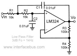
The LM324 Low-Pass Filter

I know, I know… It has been far too long since my last post.

The weather is cold and rainy so it’s CIRCUIT BENDING TIME!!!

I have been working on the Kawasaki Dual-CoolKeys lately. It’s a great keyboard with many independent features. By independent I mean, the keys are tied to a different timing resistor then the drums. Also, there is the ability to have one side play one set of instruments and the other side play another set. HOW COOL IS THAT?!?!?

I was digging through the usual circuit bending suspect’s blogs and was, as always, blown away by noystoise.com. The man is a super genius. And best of all, all his circuit bent gear looks so good.

He always has a filter (or two) in his projects. So, I wanted to have one too. How hard could it be? The answer is NOT HARD AT ALL!!!

I dug up some schematics for an LM324 Quad Op-Amp low-pass filter circuit and tried it out. I ran into one major problem with the integration of the low-pass filter and the Dual-CoolKeys. The Coolkeys has the drums output as the negative terminal going into it’s internal speaker. The keys are on the positive terminal. WHAT?!?!?

I spent a day just trying to figure out why the drum beats weren’t playing into the filter.

Once I figured out that each line into the speaker was actually individual sound outputs it made things easier. However, another issue is that if you connect the two outputs together with resistors to mix the sound, it shorts out the keyboard. I don’t know if it needs higher resistor values or what but that was annoying too.

Ultimately, I think I will just run each into an amplifier and mix them after that.

Back to the low-pass filter…

The filter is a simple build. Nothing fancy. The circuit only uses one op-amp from the LM324 so you still have 3 op-amps for other things. A great thing to add would be another filter for the drums. Or a high-pass filter… We will see.

lm324 opamp low-pass filter design

lm324 opamp low-pass filter design

I bread boarded everything up and it worked great.

LM324 Low-Pass Filter

I played around a little with the values of the potentiometer and the other resistors. It took a while to find the right balance. If I remember correctly, the original schematic worked pretty well though.

LM324 Low-Pass Filter

It’s a great little circuit and super easy to build. Try it out and let me know how it goes.

Happy bending!!!

lm386 – projects

I just got a batch of lm386 audio amplifying ic’s. I’m pretty stoked about it. Mostly because they were super cheap and I have seen them included in many applications.

Despite what you will read on many electronics forums, there are quite a few projects that you could use the lm386 for. So, I wanted to include some of them.

First off, here is one place you can find the datasheet for the lm386:
lm386 datasheet

Here is the pinout for the lm386:
lm386 pinout diagram

Interesting project #1
lm386 smashdrive distortion pedal
This looks simple enough to build and has a few options for modification.

Interesting project #2
Using the lm386 as an oscilator
This step by step shows how you can produce a square wave from the lm386. This is a good way (and cheaper?) to do something other than going the common 555 route.

Interesting project #3
DIY Tremolo Effects Pedal Schematic Using lm386
In this example, the author uses a lm386 as an amplifier and then oscillates the power of the audio amp with a 555 timer IC. However, you could use the second interesting project to create the oscillator using another lm386.

Here a link to the original article:
DIY Tremolo Effects Pedal Schematic Using lm386 and a 555 timer

Conclusion:
Although the experts will say things like “don’t bother with the noisy little lm386 audio amplifier” or “the lm386 isn’t an op-amp it’s an audio amplifier! There are some many better suited IC’s” or whatever, we can clearly see that there are many things that the beginner can do with a handful of them.

One could easily create an simple syth with an lm386 generating a square wave as the primary voice. With a little effort, another lm386 oscillator could be made to modulate the volume (i.e. Tremolo) or the pitch (i don’t know what that’s called). Finally, everything could be distorted through a distortion circuit and amplified to a little speaker or headphone jack.

Good luck!!!

Simple Wah Circuits and Schematics

I wanted to post some wah circuits that I found.

Wah circuit #1

This first one is from a great page that tells you everything you ever wanted to know about WAH PEDALS.
wah circuit 1

View the whole article here:
http://www.geofex.com/article_folders/wahpedl/wahped.htm

Wah circuit #2

This next one is from diyguitarist.com
dunlop wah circuit schematic

I found the article here:
wah schematic

Wah circuit #3

This one just looked really simple. I think you can even buy the kit from the page.
simple wah circuit schematic #3

View the article here:
wah wah circuit kit project

That’s just a few of the many that I found. Again, I really like the first link because the page really goes into what it takes to get that classic wah wah sound. Including, where to get the 500mH inductor. (hint: it’s actually a audio transformer from Radio Shack… well half of it anyway)

I hope this helps somebody out.

Good luck!

PT2399 – Echo – Delay

So far, every time I test an audio circuit I have been running it through my guitar amp and pedal board. I have some effects pedals that make everything sound AMAZING. It doesn’t matter if it’s just obnoxious noise or beeps, bops, bleeps and boops or what. It all sounds great.

I have a Boss delay pedal and an Ibanez chorus pedal, wah pedal, distortion… amongst others.

The key is the delay pedal. No matter the input is, the delay pedal creates a rhythmic pulsing that is just heavenly.

So, I wanted to add an echo/delay effect to all the stuff I do from now on. It just seems like the right thing to do. I won’t always have a delay pedal and amp to process the sounds so, naturally, integrating one into the circuit is a must.

PT2399 Echo/Delay Audio Processor IC

Enter the PT2399. I found a delay IC that you can get for relativly cheap on Ebay (10 chips for $11 and free shipping from the seller “connectors_usa”  http://myworld.ebay.com/connectors_usa/).

Below is the datasheet and pinout info.  The PDF lists the application of the delay circuit which I have included a pic of.

PT2399 – Pinout and Datasheet

You can find the Datasheet and pinout information at…
http://www.ic-on-line.cn/iol_pt2399/pdfview/180639.htm.

PT2399 – Echo Application Circuit

You can find the entire PDF here…
http://kr.ic-on-line.cn/IOL/datasheet/pt2399_180639.pdf

I’m gonna order a batch and try and rig up a delay circuit. I will of course write about the process and let everyone know how it went.