I know, I know… It has been far too long since my last post.
The weather is cold and rainy so it’s CIRCUIT BENDING TIME!!!
I have been working on the Kawasaki Dual-CoolKeys lately. It’s a great keyboard with many independent features. By independent I mean, the keys are tied to a different timing resistor then the drums. Also, there is the ability to have one side play one set of instruments and the other side play another set. HOW COOL IS THAT?!?!?
I was digging through the usual circuit bending suspect’s blogs and was, as always, blown away by noystoise.com. The man is a super genius. And best of all, all his circuit bent gear looks so good.
He always has a filter (or two) in his projects. So, I wanted to have one too. How hard could it be? The answer is NOT HARD AT ALL!!!
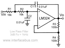
I dug up some schematics for an LM324 Quad Op-Amp low-pass filter circuit and tried it out. I ran into one major problem with the integration of the low-pass filter and the Dual-CoolKeys. The Coolkeys has the drums output as the negative terminal going into it’s internal speaker. The keys are on the positive terminal. WHAT?!?!?
I spent a day just trying to figure out why the drum beats weren’t playing into the filter.
Once I figured out that each line into the speaker was actually individual sound outputs it made things easier. However, another issue is that if you connect the two outputs together with resistors to mix the sound, it shorts out the keyboard. I don’t know if it needs higher resistor values or what but that was annoying too.
Ultimately, I think I will just run each into an amplifier and mix them after that.
Back to the low-pass filter…
The filter is a simple build. Nothing fancy. The circuit only uses one op-amp from the LM324 so you still have 3 op-amps for other things. A great thing to add would be another filter for the drums. Or a high-pass filter… We will see.
I bread boarded everything up and it worked great.
I played around a little with the values of the potentiometer and the other resistors. It took a while to find the right balance. If I remember correctly, the original schematic worked pretty well though.

LM324 Low-Pass Filter
It’s a great little circuit and super easy to build. Try it out and let me know how it goes.
Happy bending!!!


I’m having trouble reading this diagram, would you mind breaking it down for me? I think I understnd that the R’s are resistors, and the C are capacitors, and the Lm324 is the actual chip. But the V in is voltage in yeah? So would this be Voltage from a 9 volt battery or something? and the |li marks are the speakers yeah? so would that be a speaker out from near R4 and a speaker out from near C2? thanks in advance
Could you tell me what the voltage in and voltage out exactly is? I’m assuming a 9volt battery for the voltage in?
where did you actually place the pots? R1,R2,R3,R4?
I don’t really remember. I had to re soder the pots a couple of times because things weren’t working right. But if you look at the schematic, you can kind of see what is going on… experiment with a few different placements.
You won’t destroy the IC… but you may have to disconnect the power if you test a connection and things go funny. I remember having to do that quite a bit with this circuit.
If I get some time I will look through my notes and see if I can figure out what I ended up doing.
Thanks for the comment.
Cheers!
Vin and Vout is the signal coming into and out like the voltage from a microphone. The power supply pins should be noted on the schematic which makes a difference if the input sinusoid rides on a 0Vdc bias or if it needs to be bumped up to a + bias with an input amp or voltage divider.
Hey
Could you put the breadboard pictures up again please?
Thanks
didnt work for me. i just got some bass and tistorced bits. i used an an7522 ci to amplifier. im trying alot to make my subwoofer as i sold mine.