DIY Drum Machine – Circuit Bending

I have been working on a diy drum machine for a while now. I wanted to post this video to show it’s functionality.

The core of this drum machine is from an electronic drum stick. You swing the stick and it makes drum sounds. The stick made 3 sounds; Snare, bass drum, and high hat.

DIY Drum Machine

When you swing the drum stick, it plays a snare sound. There are two buttons on the stick, that when pressed AND the stick is swung, play two more sounds. So this was easy to hook up to a 3-way switch with up as one button, down as another button, and middle was just like swinging the drum stick without pressing a button.

DIY Drum Machine

I rigged it up to a 555 timer and a 4017 decade counter and some pots and switches, and away it went. There is still some glitching that happens I think because of some switches which aren’t wired to ground to de-bounce them.

DIY drum machine - time signature controlerDIY drum machine - switches to control sound typeDIY drum machine - 555 timerDIY drum machine - 4017 decade counter

The 555 timer triggers the drum sound and advances the 4017. The 4017 sends a pulse through one of 10 3-way switches to hold the particular sound. The sound selection is set with the 3-way switch. I hope that makes sense.

Like I said, it’s a work in progress.

DIY drum machine - control board layout design

The case is from a kids toy (big surprise, I know). It was a light box for tracing. It use to have two lightbulbs inside and a semi-transparent screen. The cool thing about is that it has a battery compartment built in. All I had to do was modify it for the voltage I was using. I just shrunk it down. Easy (yeah right).

I painted it up white first and then spray painted a stencil of a fist on top of it. The body was also painted red. The final step for the paint job was to do some clear coat. All in all, a pretty sweet paint job.

Circuit Bending a DIY Drum Machine

In this video, you can see holes for the LEDs that will indicate which point in the sequence it’s at. I am having a heck of a time with that. It seems like, when connected, the sound plays but the LEDs don’t light up. I don’t know if it’s a lack of current or what. I have tried the LEDs in series and in parallel. Neither work now. The joke is, it all worked at one point when it was on a bread board. Upon soldering everything up, everything started changing. I suppose that is the nature of the beast.

I would love to hear your thoughts.

Happy Bending,
Nick

Arduino Sequencer

NEW POST!!!

To quote noystoise…

wow, its been a long time since i have posted anything here.

It has been ages since my last post. So much has happened (Including planning a wedding and getting married). With that said, I have still been circuit bending and building things.

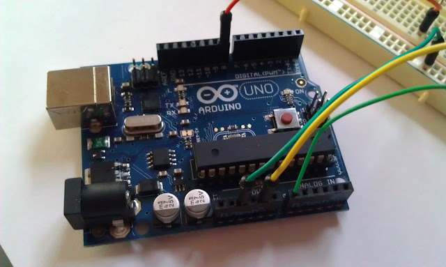
My Arduino Uno Micro-Controler

Recently, I purchased an Arduino Uno micro-controller. This thing is awesome. It doesn’t have much to do with true circuit bending (I know someone will have a problem with that) but it is insanely powerful.

Here is what I have been playing around with in the last few weeks.

This little Arduino Sequencer project that I have been working on is super simple to build. Really all you need is an Arduino Uno (and a computer to program it with), breadboard, speaker, potentiometer (any value) and some wires.

All of the functionality comes from the programming. The code is simple too. Basiclly, you use the built in tone generator (it’s just a square wave generator) to read the value of a potentiometer and place the value of that the potentiometer into a variable. Then you play a tone based on that value, pause, play another tone, pause, play another, etc.

The subsiquent tones are based off the original tone, they are just multiples of that first value.

The program loops and starts all over again. That’s it!

Arduino uno diy sequencer

Here is the link to the tutorial that I followed originally. It has some schematics and in depth instructions about how to set it up and how the code works.
Arduino Tone Follower Tutorial

Here is the code:

/*
SecondHandSynth Digital Arduino Sequencer
https://secondhandsynth.wordpress.com/

Plays a pitch that changes based on a changing analog input

circuit:
* 8-ohm speaker on digital pin 8
* Breadboard
* Some resistors and wire

This example code is in the public domain.

Original code before modification came from
http://arduino.cc/en/Tutorial/Tone2

*/

void setup() {
// initialize serial communications (for debugging only):
Serial.begin(9600);

//boot up sound
int var = 100;
while (var < 500)
{
tone(8, var, 50);
delay(150);
var=(var+80);
}

}

void loop() {
// read the sensor:
int sensorReading = analogRead(A0);
int delayTime = 175;
int durationTime = 5000;

// print the sensor reading so you know its range
Serial.println(sensorReading);

// map the pitch to the range of the analog input.
// change the minimum and maximum input numbers below
// depending on the range your sensor's giving:
int thisPitch = map(sensorReading, 0, 1023, 50, 2000);

// print the mapped range
Serial.println(thisPitch);

// play the pitch:
tone(8, thisPitch * 2.5, durationTime);
delay(delayTime);
tone(8, (thisPitch * 2), durationTime);
delay(delayTime);
tone(8, (thisPitch * 1.5), durationTime);
delay(delayTime);
tone(8, (thisPitch), durationTime);
delay(delayTime);

//second string
thisPitch = thisPitch * .5;

tone(8, thisPitch, durationTime);
delay(delayTime);
tone(8, (thisPitch * 1.5), durationTime);
delay(delayTime);
tone(8, (thisPitch * 2), durationTime);
delay(delayTime);
tone(8, (thisPitch * 2.5), durationTime);
delay(delayTime);

//second string
thisPitch = thisPitch * 1.5;

tone(8, thisPitch, durationTime);
delay(delayTime);
tone(8, (thisPitch * 1.5), durationTime);
delay(delayTime);
tone(8, (thisPitch * 2), durationTime);
delay(delayTime);
tone(8, (thisPitch * 2.5), durationTime);
delay(delayTime);

//second string
thisPitch = thisPitch * .5;

tone(8, thisPitch, durationTime);
delay(delayTime);
tone(8, (thisPitch * 1.5), durationTime);
delay(delayTime);
tone(8, (thisPitch * 2), durationTime);
delay(delayTime);
tone(8, (thisPitch * 2.5), durationTime);
delay(delayTime);

}

Try it out for yourself and let me know how it works. If you have any questions, don’t hesitate to ask.

Thanks for reading and HAPPY BENDING!

Toy keyboard project – Wah circuit

I am working on this new/old/hearandnow project.

I am trying to take a crappy second hand synth keyboard that I got from a new Value Village a few weeks ago.
second hand synth from Value Village #2

I want to repackage it using only one (maybe two) of the octaves on the keyboard. I will just use a simple pitch bend (1M pot) connected to the timing of the motherboard to get whatever ocatave leval I am looking for. The basics for any bend really.

second hand synth drum patterns - Some are doubled up

My main goal is to add a few simple effects to the keyboard output and the amplify it. Sounds simple.

Attempt 1 – Simple Low Pass Filter

The reality, for me anyway, has been a bit of a nightmare. I can’t seem to do anything except volume control. The last few attempts have been low pass filters. I started with a simple RC (Resistor – Capacitor circuit) circuit where the resistor was a 10k volume pot in series with the signal out and a .1uF capacitor branched off to ground. I played with the values of the potentiometer and capacitor until I found something that looked like it would work.

here is a basic schematic:
Simple Low Pass Filter for Toy Synth Circuit Bend

It didn’t really work. I posted some “help me I’m an amateur and an idiot” posts on an electronics forum. They told me I needed to amplify the output. I read that last bit after I had started onto another more complicated project.

you can veiw the “help me I’m an amateur and an idiot” post here:
Low pass filter – help me!!!

Attempt 2 – Simple Active Low Pass Filter

The next thing I tried was an active low pass filter. This involves an op-amp… apparently.

This is what it looked like on paper.
Active Low Pass Filter Schematic

I also posted some more “help me I’m an amateur and an idiot” posts here:
Active low pass filter – Help me!!!

Now I am onto bigger and better things… If I could only get them to work.

Attempt 3 – Simple Wah Filter Circuit

Here is the schematic to a simple wah pedal circuit using the TL082 dual operational amplifier.
Simple Wah Circuit Schematic using the TL082

I bread boarded this all up and all it did for me was, again, volume control… more control than the other two examples… but still just plain old volume.

At first I was just stoked that something was happening. Then I compared it to my guitar wah pedal. It wasn’t even close to cool.

So what did I do? You guessed it. I posted some more “help me I’m an amateur and an idiot” posts.
View them here:
wah circuit help

So that’s where I’m at with my new amazing project involving some do it yourself analog filters and a crappy second hand synth.

No real progress at all.

But I’m not giving up!